
Sean M. O’Connor and Jerome P. Lynch, Ph.D.
Department of Civil and Environmental Engineering, University of Michigan
Mohammed Ettouney, Ph.D.
Weidlinger Associates, New York, NY
Gwen van der Linden, Ph.D.
SC Solutions, Sunnyvale, CA
Sharada Alampalli,
Prospect Solutions, Loudonville, NY
 Wireless sensor technologies offer inexpensive sensors that can be installed in bridges with great ease. Permanent wireless monitoring systems provide bridge response data from which bridge behavior can be understood and structural conditions assessed. This study presents a permanent wireless structural monitoring system under development at the University of Michigan that is deployed on the Telegraph Road Bridge in Monroe, Michigan to showcase the reliability of wireless sensors in harsh field conditions and prove their effectiveness in aiding bridge owners in their decision-making.
The Telegraph Road Bridge (TRB), owned and managed by the Michigan Department of Transportation, is a multi-girder concrete deck composite steel bridge built in 1973 that carries two lanes of I-275 northbound traffic. Monroe is an area of southeastern Michigan that experiences extremely heavy trucks on its roads and bridges due to the region’s large manufacturing industry and its close proximity to the Canadian border in Detroit. The length of the TRB is approximately 224 ft. (68.28 m). It is designed with three main spans: the end spans are 48 ft. (14.63 m) long and span from the bridge abutments to support piers with their spans cantilevering 6 ft. (1.83 m) past the piers, while the main span of 140 ft. (42.67 m) suspends from the cantilevered ends of the wing spans using pin and hanger assemblies. The bridge has 7 steel girders in composite action with an 8 in. (20.32 cm) reinforced concrete deck. The bridge has a skew angle of 57 degrees.
The TRB shows signs of deterioration from 40 years of service. The deck is severely cracked with potholes in its top deck surface. There are fatigue cracks in the girder webs where transverse cross frames are welded to the girders. In addition, some section loss has occurred in one girder on its lower flange immediately above its bearing. Other critical problem areas include the fracture-critical pin and hanger assemblies, which lack redundancy in their design. Loss of composite action between the deck and the girders can lead to potentially unsafe conditions.
 |
| Plan view of the Telegraph Road Bridge with details of the wireless monitoring system |
Three main parameters were measured by the wireless monitoring system: strain, acceleration and temperature. Deck strain was measured to understand its response to truck loading and thermal variations. Strain measurements through the height of the steel girder-concrete deck cross section were used to identify the neutral axis of the section and assess the degree of composite action. Strain measurements were collected in four hanger plates to assess stress concentrations at the pins, axial strain under truck loading and flexural strain in the plate that would suggest locking in the pin-hanger plate interface. Finally, accelerometers were used to provide dynamic response data for updating finite element models.
 |
|
Narada wireless sensor node (left) with the fully packaged wireless sensor node in a water-tight enclosure (right) |
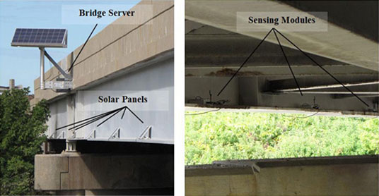
A network of 37 Narada wireless sensor nodes, developed at the University of Michigan, was installed on the TRB along with an on-site server to manage the sensor system. The node provides 16-bit data acquisition on 4 independent channels and communicates wirelessly. The Narada node, housed in a watertight enclosure, has a lead acid battery, sensor signal conditioning circuitry and power harvesting circuitry. A multi-crystalline solar panel continuously recharges the battery. In total, 15 accelerometers, 50 metal foil strain gage sensors, 6 Bridge Diagnostics Intelliducers, and 6 thermistors are installed on the TRB.
 |
| Solar panels on outer girder #7 surface shown with the monitoring system server (left) and wireless nodes magnetically mounted to steel girder flanges (right) |
Fourteen uniaxial (vertical) accelerometers positioned along the outside perimeter of the main span identify the modal parameters. A single tri-axial accelerometer is installed at the center of the bridge. All acceleration signals are conditioned with a 25 Hz low pass filter and 5 times amplification. These measurements provide a modal analysis of the bridge with modal characteristics used to update finite element models.
Metal foil strain gages positioned along the height of the steel girders in 6 locations measure axial strain in the beams due to bending. The strain gage sets were installed along girders #2 and #6 over each pier and at mid-span for the composite action assessments. Each strain gage was configured into a quarter Wheatstone bridge with 100 times amplification. Strain gages were also placed 3, 27 and 51 inches from the bottom flange of the web. Bridge Diagnostics Intelliducers installed on the bottom surface of the deck measure the strain directly above the points where the steel girder strain is measured. On the hanger plates, additional strain gages measure out-of-plane bending, in-plane bending and axial strain.
 |
| Metal foil strain gages bonded to girder #2 at mid-span |
Bridge temperature is measured using three thermistors at each of two locations. Those at the center of the bridge at girder #4 measure the girder and deck temperature, while those at the outer bridge surface at the center of girder #7 take readings where there is direct southern exposure during the day.
The sensing nodes are managed by a base station consisting of a PC-104 single board computer with wireless connectivity to the sensor nodes, a lead acid rechargeable battery and a 3G USB cellular modem. The base station is fully powered by a 12V multicrystalline solar panel. The server system, encased in a large water tight enclosure, is mounted to the south fascia of the bridge deck. Data is collected by the computer and stored until it is transmitted to a server at the University of Michigan by cellular modem. The complete wireless monitoring system is configured to record bridge data on a user-defined schedule. Acceleration data is sampled at 200 Hz and strain and temperature data is sampled at 100 Hz. System end-users can remotely connect to the bridge base station to implement data collection strategies.
To propel the sensor data into the realm of decision-making, a computational framework aggregates data and extracts information pertinent to bridge management. Towards this end, the bridge wireless monitoring system is part of a larger Internet-based cyber-environment constructed in two tiers. The lower tier contains the wireless sensor network at the bridge that is dedicated to collecting response data and environmental data. The upper tier, which is remotely accessible via the bridge’s 3G cellular connection, operates around a centralized data repository called SenStore. This provides a database for the management of bridge data as well as a standardized platform for data sharing among data processing applications. SenStore combines sensor data with bridge design information (e.g., geometric details, material properties) and its application programming interfaces permit data processing tools to extract the information it needs. With data about the bridge stored in one database system, a complete decision-making tool set can be applied to bridge data to aid owners in critical management decision and in risk management. This tool set is currently under development at the University.
SC Solutions and the University of Michigan collaborated on and managed this project through a joint venture. For further information, please contact Alex Krimotat, SC Solutions, at Alex@SCsolutions.com or 408-617-4555.
This article is reprinted with permission from The Monitor.